Some Thoughts on Inexpensive Drone Borne Gas SensorsRichard Heurtley2018-10-04 richard@heurtley.com The Sensor Package ControllerThere are two inexpensive well-supported controller circuit boards available: the Arduino and the Raspberry Pi. Either could be used as a sensor controller but they are quite different. The Arduino is a low-level microcontroller while the Raspberry Pi is a full-blown Linux computer.Strengths of the Arduino
Strengths of the Raspberry Pi
The Arduino Mega draws 80ma of power at its five volt nominal power supply and has a number of sleep options to reduce power. The Raspberry PI 3 B+ draws a minimum of 400ma of power at five volts. The Raspberry Pi 3 B+’s built-in WiFi adapter antenna is a marvel of circuit engraving but is also quite small. Its range may not be sufficient for a drone application. Both controllers have a wide variety of stackable add-on circuit boards called “hats” for the Raspberry Pi and “shields” for the Arduino. A portable wireless gas sensor application requires:
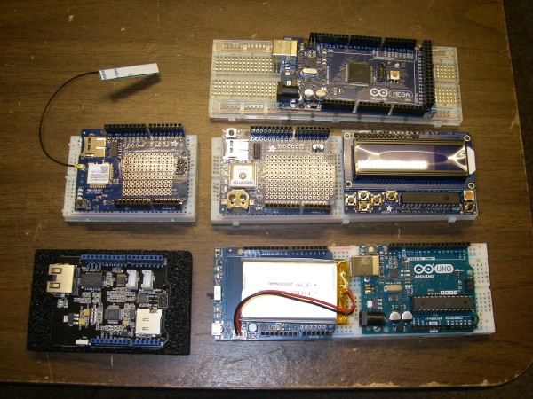
Top row: Arduino Mega
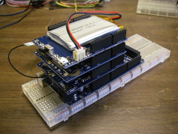
A completed stack of the Arduino Mega, battery pack, WiFi adapter, and GPS receiver looks like this:
The WiFi and GPS shields each have prototyping area and require an external antenna. When mounted on a drone the GPS antenna should be on top and the WiFi antenna should be on the bottom. Adafruit is a good outfit from which all manner of controllers, add-ons, and sensors may be obtained: Components are also available from various Amazon vendors. Adafruit generally has example code for both controllers for its products. The issue that may compel the choice between a Raspberry Pi and an Arduino may have nothing to do with the controllers’ physical specifications but with the difficulty of writing the software. The Arduino is programmed in C++ although the object oriented features of C++ aren’t heavily used because they make larger executable images. The Adafruit code examples for the Raspberry Pi are in Python which may be easier for non-experts. Software libraries that implement standard networking protocols are available and it would make sense to use them. The TCP/IP networking standard is universal. The MQTT machine-to-machine data transfer protocol would be a good choice for transferring the acquired data off the sensor package: WiFi is not the only wireless technology available. The ZigBee protocol could be used although its range is less than WiFi. If there is coverage then commercial cellular Internet access could be used. Both of these options would involve more exotic hardware with less support and greater programming requirements than WiFi. System ArchitectureA small system consists of:
The base station can be any computer that can operate in the field. If the MQTT protocol is used then the free Eclipse Mosquitto implementation runs under Linux, macOS, and Windows: The base station could be configured to act as a WiFi access point for the sensor package and clients but it may be easier to use a separate WiFi router and connect the base station to it wirelessly or with a CAT5 cable to one of the router’s LAN ports. WiFi routers frequently have 12 volt power supplies and can be run from a 12 volt battery with a little care. When researching this use the search terms “wireless router” and not “wireless access point” because there is a difference. An example client is an Android smartphone running the MQTT client app MQTT Dash: https://play.google.com/store/apps/details?id=net.routix.mqttdash&hl=en_US An interesting fact about a small system is that the Internet is not involved. This means the WAN port of the WiFi router can be ignored. A packet of data transmitted from the sensor package to the base station might include:
SensorsThere are two kinds of gas sensors. Smart sensors calculate a concentration value, often in parts-per-million, and connect to a controller in a high level way like a serial or I2C bus. Dumb sensors don’t do any calculation and require the controller to calculate the concentration from the sensor’s resistance or output voltage.Gas sensors generally require a small heater to energize the sensing material. The power draw of sensor heaters must be included when calculating the sensor package battery size and run times. 150ma at five volts is typical of the simple gas sensors I’ve worked with. I have played with two inexpensive gas sensors: the MQ-4 methane sensor and the MH-Z14A carbon dioxide sensor both made by Winsen: https://www.winsen-sensor.com/products/semiconductor-gas-sensor/mq-4.html https://www.winsen-sensor.com/products/ndir-co2-sensor/mh-z14a.html There are many sensors in the MQ series that detect different gases. A list is available here: https://www.winsen-sensor.com/products/semiconductor-gas-sensor/ The MH-Z14A is a smart sensor that calculates a parts-per-million value. It has several interfaces including a serial interface that connects easily to either an Arduino or a Raspberry Pi. The output is from zero to 5000ppm of carbon dioxide. In fresh air it reads 400ppm. The MQ-4 I bought is mounted on a small circuit board connected in series with a variable resistor: https://www.amazon.com/Phantom-YoYo-Arduino-compatible-Sensor/dp/B00AFQB69I Its output is a zero to five volt signal across the variable resistor. An analog to digital converter is required to sample it. The Arduino has six A/D inputs built-in. I bought this 16 channel A/D converter hat for the Raspberry Pi I’m working with: http://alchemy-power.com/pi-16adc/ The Arduino’s analog inputs measure from zero to five volts. The Raspberry Pi A/D hat’s analog inputs measure from zero to 2.5 volts so when working with five volt signals it’s necessary to divide the voltage with a pair of resistors in series. Some of the voltages I’m working with are slightly greater than five volts so I’ve been dividing the voltages into roughly a third using a 10Kohm and a 22Kohm resistor (what I had on-hand) in series, measuring the voltage across the 10Kohm resistor, and calculating the full voltage by multiplying the reduced voltage by (22K+10K)/10K. A temperature sensing “thermistor” is a resistor whose resistance varies as a function of temperature. The MQ-4 could be called a “methristor” because it’s a resistor whose resistance varies as a function of methane concentration. To determine the sensor resistance you put it in series with a resistor of known resistance, apply a known supply voltage across the two resistors, and measure the voltage across the known resistor. The resistance of the sensor is calculated as follows: amps = Vknown / Rknown Vsensor = Vsupply – Vknown Rsensor = Vsensor / amps The mounted MQ-4 I have is connected in series with a “variable resistor” but in this case the “variable resistor” is actually the “known resistor”. It’s adjusted to a fixed value, in this case 4.7Kohm, and left alone. Version 1.4 of the MQ-4 manual is available here: Page 4 has a chart of the MQ-4 sensitivity curve. If: Rs = the resistance of the sensor in the presence of methane Rz = the resistance of the sensor in the absence of methane Then: log10(Rs / Rz) is roughly linearly proportional to log10(ppm) You can see the relationship is nearly a straight line on the chart. I printed out a large copy of the sensitivity curve chart and used a ruler to measure the ratio values from 300ppm to 10Kppm. I then wrote a program to calculate the log10(ratio)/log10(ppm) relationship as a polynomial. It’s not exactly a straight line so I used three terms. But that’s not sufficient because the sensitivity curve chart is only for the standard environmental conditions of 20C and 55% relative humidity. The chart to the right of the sensitivity curve chart shows how the sensor’s resistance should be adjusted for different temperatures and humidity values. I again printed out a large copy, got out my ruler, and wrote a program to turn those curves into more polynomial equations. Here’s the resulting process:
Here’s the actual C language source code I use in my program:
I divide the temperature in degrees Celsius and the relative humidity from zero to 100% by 100 to get values from zero to one. This makes the polynomial coefficients larger and easier to work with. I save the sensor’s adjusted resistance as a returnable value. You need to know the no-methane resistance to calculate the ratio. One problem with this approach is that the relationship polynomial produces a value of about 50ppm when the ratio is 1.0. This does not mean that there is 50ppm of methane in the air and it does not mean that the sensor reads 50ppm high. The MQ-4 sensor isn’t very sensitive and only begins to kick in at about 200ppm. Any result less than 200ppm should be considered zero. At this point you’re probably thinking that it would be a lot less work to find a smart version of the sensor. Here is one that connects to the controller via the I2C bus: https://store.ncd.io/product/mq-4-methane-natural-gas-sensor-adc121c-12-bit-adc-i2c-mini-module/ The problem with this sensor is that it does not have temperature and humidity sensors and does not apply the appropriate adjustment. The specification says:
The ideal sensing condition for the MQ4 is 20°C ±2°C at 65% ±5% humidity. which means the concentration values produced will deviate as the environmental conditions deviate from the standard. So to use the MQ-4 effectively you also need temperature and humidity sensors. One popular and inexpensive choice is the DHT22: https://www.adafruit.com/product/385 This connects to the controller via a digital I/O pin. The DHT22 works better on the Arduino then the Raspberry Pi because the controller has to “bit bang” the I/O pin to trigger the sensor and have it transmit the temperature and humidity values. The full-blown multitasking version of Linux running on the Raspberry Pi makes precise bit-banging timing difficult. A popular sensor that works well with both controllers is the Bosch BME280: https://www.bosch-sensortec.com/bst/products/all_products/bme280 as packaged by Adafruit: https://www.adafruit.com/product/2652 This connects to a controller over the I2C bus and provides temperature, relative humidity, and air pressure. When investigating these sensors do not confuse the inferior DHT11 and BMP280 sensors with the superior DHT22 and BME280 sensors. Here’s a picture of a data collection box containing a Raspberry Pi 3 B+, power supply, LiPo backup battery, 16 channel A/D hat; and the MH-Z14A, MQ-4, and BME280 sensors. (Actually it’s a BME680 but they look the same.) If packaged differently and with a GPS module added this would make a good drone payload.
|