A Drone-Borne Thermal Imager AssemblyRichard Heurtley2018-12-21 richard@heurtley.com OverviewThe Melexis MLX90640 is a 32x24 pixel infrared thermal imager with a temperature range of -40 to 300 degrees Celsius. It uses the two pin I2C bus for communication and draws 23ma at 3.3 volts:https://www.melexis.com/-/media/files/documents/datasheets/mlx90640-datasheet-melexis.pdf Single units are $45 from DigiKey: https://www.digikey.com/en/product-highlight/m/melexis/mlx90640-fir-sensor A convenient breakout board, with an MLX90640 installed, is $70 from Sparkfun: https://www.sparkfun.com/products/14844 I was evaluating the MLX90640 as a non-contact temperature sensor for boiler room monitoring when, after seeing a demo, a friend inquired if one could be mounted on a drone. Knowing his enthusiasms I call the result CoyoteCam (TM). System Hardware
System Software
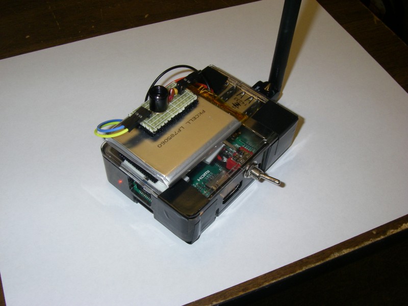
Network ArchitectureThe thermal imager assembly and the Windows computer both attach to the wireless access point which serves as an intermediary relaying data between the two ends. The wireless access point does not need to have Internet access to work in this application.The completed assembly weighs six ounces. The antenna is six inches long:
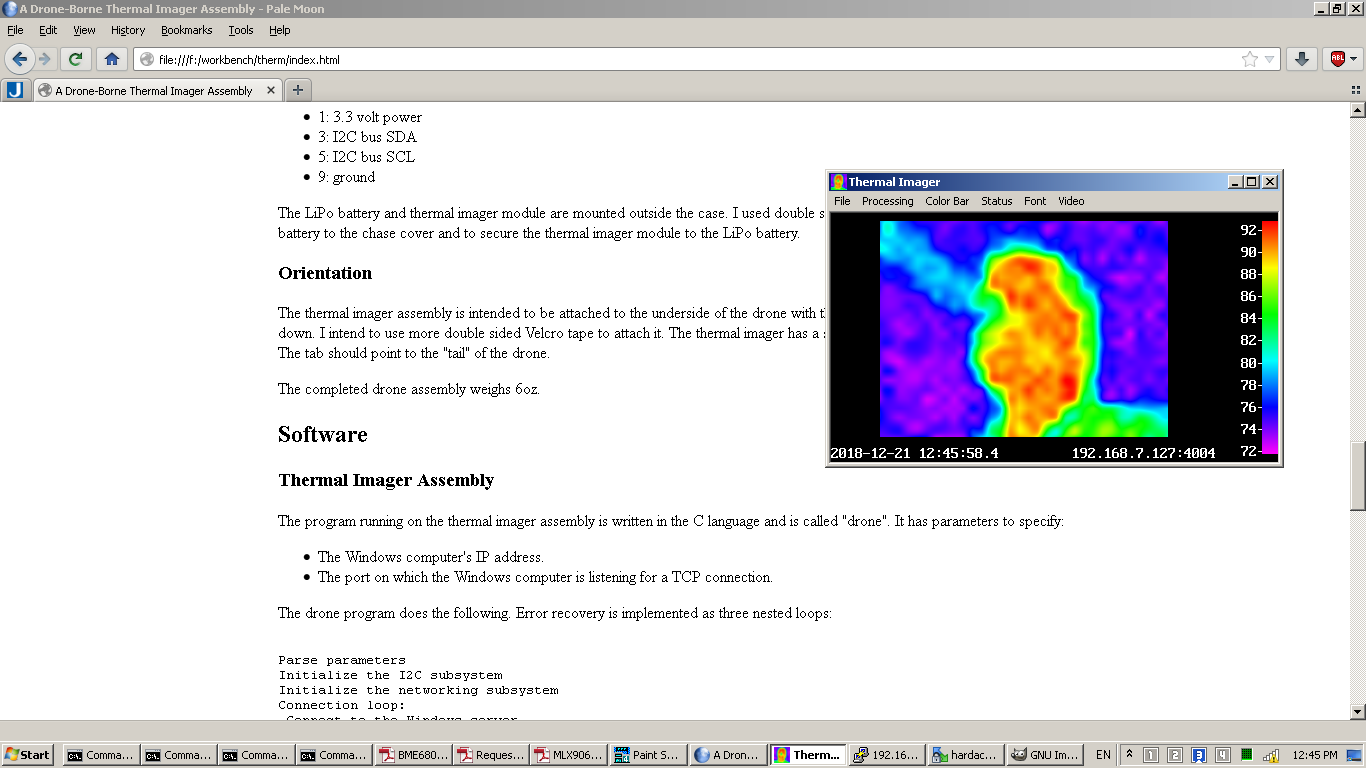
A Windows computer screenshot:
HardwareThermal Imager Assembly Components
Some models of the Raspberry Pi have built-in WiFi. These models have an antenna engraved into the circuit board which, while extremely clever, does not have great range. Range is important in a drone application so I chose a Raspberry Pi model with USB ports and no built-in WiFi, and a USB WiFi adapter with an external antenna. The LiPo battery I chose is this $15 unit from Adafruit: https://www.adafruit.com/product/328 The LiPo charge controller/power supply module is this $20 unit from Adafruit: https://www.adafruit.com/product/2465 The USB WiFi adapter is this $20 unit from Adafruit: https://www.adafruit.com/product/1030 The same WiFi adapter *may* be only $8 from Amazon. The reviews say that it isn't always the same model: https://www.amazon.com/Long-Range-WiFi-Antenna-Raspberry/dp/B00FADTN14 $8 plastic case from Adafruit: https://www.adafruit.com/product/2258 Power SupplyIn the interest of brevity the LiPo charge controller/power supply module will be abbreviated "CC/PS".The CC/PS has the following connections:
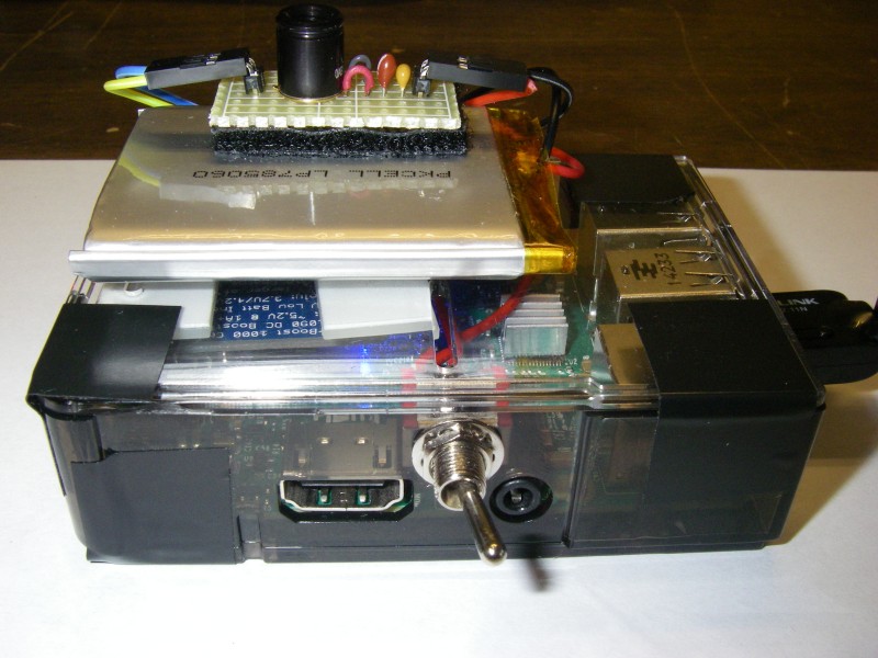
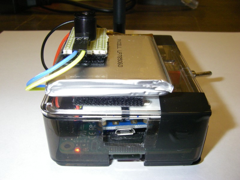
The 5 volt micro USB connector is used to charge the LiPo battery and power the assembly from an external power supply. If the Raspberry Pi's built-in micro USB connector is used the assembly will be powered but the LiPo battery will not be charged. The Adafruit LiPo battery comes with a connector that conveniently plugs into the Adafruit CC/PS. The 5.2 volt output power and ground lines are connected to the Raspberry Pi GPIO connector's 5 volt and ground lines, pins 6 and 4 respectively. The CC/PS is on by default. There is an enable line that turns of the CC/PS off when the line is connected to ground. I used a toggle switch to do this, a small slide switch would be lighter, and connected it to GPIO connector ground pin 14. Do not connect the battery until the CC/PS enable switch is wired up. Component MountingThe toggle switch and CC/PS are mounted inside the cheap plastic case. I drilled a hole and mounted the toggle switch above and between the HDMI and audio jacks:
The CC/PS is mounted upside-down on the case cover above the Raspberry Pi's micro SD card slot. I used a nibbling tool to cut out a section of plastic to expose the CC/PS's micro USB connector.
I used a 40 pin ribbon cable header: to attach wires to the following GPIO lines: Connected to the CC/PS:
Connected to the CC/PS enable switch:
Brought outside the case to the thermal imager:
The LiPo battery and thermal imager module are mounted outside the case. I used double sided Velcro tape to secure the LiPo battery to the chase cover and to secure the thermal imager module to the LiPo battery. OrientationThe thermal imager assembly is intended to be attached to the underside of the drone with the WiFi adapter's antenna pointing down. I intend to use more double sided Velcro tape to attach it. The thermal imager has a small tab that indicates image "down". The tab should point to the "tail" of the drone.SoftwareThermal Imager AssemblyThe program running on the thermal imager assembly is written in the C language and is called "drone". It has parameters to specify:
The drone program does the following. Error recovery is implemented as three nested loops:
If there's an error acquiring a frame from the thermal imager
then the program exits the frame loop and reinitializes the
thermal imager.
If there's an error transmitting a frame to the Windows computer then the program jumps out of the frame and thermal imager initialization loops and reconnects to the Windows computer. The source code of the drone program is here. The drone program compiles and runs under both Windows and Linux: The drone program is automatically started when the Raspberry Pi is turned on. This line in the /etc/rc.local file:
assumes the user identity "hardack" and invokes script /home/hardack/droneloop which is:
The infinite while loop guarantees the drone program is
always running in case there's an error condition the
program doesn't catch.
Windows ComputerThe program running on the Windows computer is also written in the C language and is called "therm". It reads a configuration file to specify the IP address and port to which it listens for a connection. This is the same IP address and port given as parameters to the drone program.The therm program is structured as several independent threads:
The net thread does the following:
The source code to the net thread is here:
When running the therm program on a Windows computer for the first time the Microsoft Windows operating system will warn you that the program is attempting to use the networking subsystem and ask if you want to add an exception to the Windows firewall. The therm program should be granted full access to the networking subsystem. Future ConsiderationsThe thermal imager could be replaced with any other 3.3 volt I2C sensor like the BME680 temperature/humidity/pressure/VOC sensor. Of course the software would be different.More GPIO lines could be bought outside like:
to support other modules and sensors. In particular a GPS receiver would provide important information in a drone application. Once a set of sensors has been standardized a custom case that exposes the sensors while protecting the circuit board(s) could be designed and made with a 3D printer. |